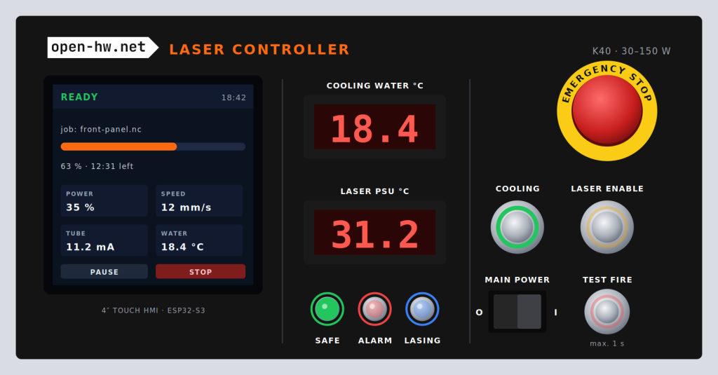
Designing a circuit, and creating a PCB for it, maybe writing the software for it, is most of the time not enough to make it usable. To make a design usable it will require some sort of enclosure where the PCB can be mounted in with all the related switches / displays etc. Where in the relative recent past the DIY enthusiast had only the option to buy a standard enclosure from a supplier, nowadays the 3D printers available for not too much money are perfectly suitable to create a custom enclosure. Design of these customs enclosures are normally done in a 3D CAD program.
The finishing touch is not only the enclosure, but also a nice front panel. For the design of front panels there are very few applications available to the DIY enthusiast. I used, until recently, the free software from Front Panel Express for the design, then I would export it as an SVG, open it in inkscape, edit all the line sizes etc, and then print it using either an inkjet printer on a label, or my preferred method now using my eufymake E1 UV printer, which can print directly on the 3D printed enclosure or on a sticker transfer sheet. All in all a pretty long process to get something designed, and unfortunately the Front Panel Design software is limited in fonts etc, which makes it more difficult to get exactly what I wanted.
Therefore I decided to see if I could design, using claude.ai, a front panel editor, which has all the functionality I am looking for, produces directly the files I need to the printers, and preferably runs in a websession.
After going through about 20 iterations, testing and verifying, I would like to present the open-hw.net Front Panel Editor.
This blog post introduces the editor, will go over the capabilities, and includes a design which you can use to try the editor out with.
Please let me know in the comments what you think, or if you find a bug, miss functionality, or anything else. Remember that everything will run locally on your computer, and that our server never sees anything you create. The editor is tested in Google Chrome, but it is expected that it will run fine in any modern browser.
Introducing the Front Panel Editor
A good front panel turns a working circuit into a finished instrument. Getting there usually means fighting a general-purpose drawing program, converting millimetres by hand, and hoping the holes line up with the parts. The Front Panel Editor on www.open-hw.net/ is made for exactly this job: you place cutouts, scales and labels in real millimetres, and it gives you the files to print the panel and to drill the enclosure.
It runs entirely in your browser. There is nothing to install, no account, and nothing is uploaded: your designs are stored on your own computer, and your current work is kept in the browser between visits.
What you can put on a panel
- Cutouts for displays, switches, connectors and lamps, including D-sub connector shells and hole patterns.
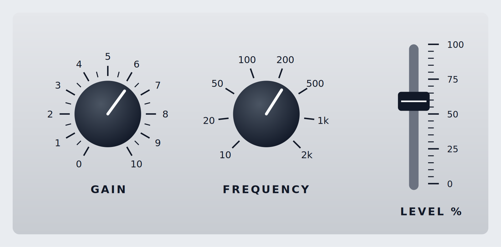
- Rotary scales for potentiometers and rotary switches, with major and minor ticks and your own labels.
- Linear scales for slide controls and bar indicators.
- Text, lines, rectangles and circles or arcs for labels, dividers and graphic elements.
Every element has exact properties in the side panel, so you can type a position instead of nudging it with the mouse. Duplicate, undo and redo work as you would expect, and a snap grid from 0.1 mm to 5 mm keeps things aligned.
Coordinates that match your drawings
All coordinates are in millimetres, with the origin (0,0) at the lower-left corner of the panel and Y pointing up, the same convention most mechanical drawings and datasheets use. For rotary scales, 0° is 12 o’clock and positive angles run clockwise, like a knob. Element rotations run counter-clockwise, as in most CAD tools.
Two kinds of files
The editor keeps the design and the printable output strictly apart.
- Save writes the design file, name.panel.svg. It keeps everything editable: every element with all its settings, text as real text, background images, and any fonts that are not built in. Open it again later, or on another computer. In Chrome and Edge, Save writes back to the same file; other browsers save a new copy to the downloads folder.
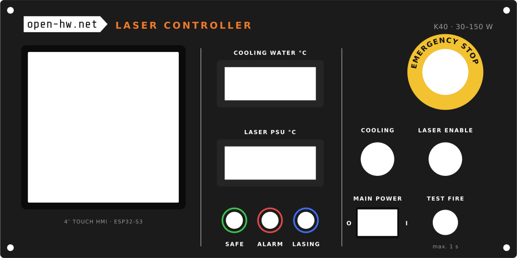
- Save for printing writes the file for the printer: SVG, or PNG at 300, 600 or 1200 dpi with an optional transparent background. All text is converted to outlines, so the printer software never substitutes a font, and no editor data is included.
When you save for printing, you choose what goes into the file:
| Content | Contains | Used for |
|---|---|---|
| Print view | Engraving, panel background and outline | UV printing onto the enclosure, or DTF sticker film |
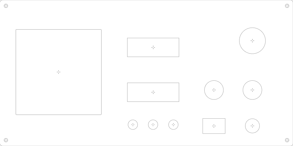
| Drilling template | Outline, cutouts and drill marks | Printing on paper and taping it onto the enclosure |
| As shown on screen | The layers you ticked under “Show” | Anything in between |
From design to finished panel
- Lay out the parts. Start from the datasheets of your display, switches and connectors, and place the cutouts first. Everything else follows from them.
- Add labels and scales. Group related controls, and use lines or coloured rings to show what belongs together.
- Print a drilling template. Print it at 100 % on paper, tape it onto the enclosure, and centre-punch every cross. Check the scale with a ruler before you drill.
- Drill and cut. The drill marks sit inside each cutout’s outline, so nothing of them remains on the panel once the hole is made.
- Print the panel. Send the print view to a UV printer, for example with eufyMake Studio, or print it on DTF sticker film and apply it to the enclosure.

Or Download the design file to edit it locally on your own computer. To make this work, download the index.html file on the editor page, and open it in Google Chrome.

Drill marks
Four styles are available: an open cross for a centre punch, an open cross with a ring, a closed cross, or none. You can set them per cutout or apply one style to all. The open cross leaves the exact centre free, which is where the punch goes.
Fonts and backgrounds
Six fonts are built in. When you are online, popular Google Fonts can be chosen from any font list; they are downloaded once and then work offline. You can also load your own .ttf, .otf or .woff file. Fonts you add are stored inside the design file, so it opens correctly on another computer.
The panel background can be a solid colour, a linear or radial gradient, or an image. To use an image, drop it onto the window.
Keyboard and mouse
| Action | How |
|---|---|
| Select, move | Click, drag (snaps to the grid) |
| Zoom | Ctrl/Cmd + mouse wheel, or pinch |
| Nudge | Arrow keys (Shift for 10× steps) |
| Duplicate, delete | Ctrl/Cmd + D, Del |
| Undo, save | Ctrl/Cmd + Z, Ctrl/Cmd + S |
| Deselect | Esc |
Tips for good results
- Check every cutout size against the datasheet of the actual part you bought. Panel-mount parts with the same name can differ by a millimetre.
- Leave room for the parts behind the panel, such as nuts, terminals and the PCB, not only for what you see on the front.
- On a dark panel, colours need a white underbase to stay bright. Check how your printer software handles this before a final print.
- Do a test print on paper or a scrap panel first. Text height and line weight look different at real size than on screen.
A drilling template is only as accurate as its print. Turn off “fit to page” scaling, and measure a known dimension on the paper before you drill.
Free and open
The Front Panel Editor is free to use, and released under the GNU GPL v3 like the rest of www.open-hw.net/. The bundled fonts are under the SIL Open Font License (DejaVu under the Bitstream Vera licence), and text-to-outline conversion uses opentype.js (MIT).